Welcome to the TEM6 Installation Manual. This guide provides comprehensive instructions for installing, maintaining, and operating the TEM6 series air handlers.

1.1 Overview of the TEM6 Series
The TEM6 series is a line of convertible air handlers designed for flexibility and energy efficiency. These units are suitable for installation in various spaces, including closets, utility rooms, and attics. The series offers models like the TEM6 A0B24H21S and TEM6 A0D48H41SB, catering to different heating and cooling demands. Known for their compact design and quiet operation, TEM6 units are ideal for residential and light commercial applications. Their versatility allows for easy integration with existing HVAC systems, making them a popular choice for modern installations.
1.2 Importance of Proper Installation
Proper installation of the TEM6 series is crucial for ensuring safety, efficiency, and optimal performance. Incorrect installation can lead to system malfunctions, reduced energy efficiency, and potential safety hazards. Adhering to the manufacturer’s guidelines ensures compliance with safety standards and warranty requirements. A well-installed system also enhances reliability, minimizes maintenance needs, and prolongs the unit’s lifespan. Always follow the detailed instructions provided in this manual to guarantee a safe and efficient setup of your TEM6 air handler.

Safety Precautions and Guidelines
Always disconnect power before starting work. Follow all local codes and regulations. Use proper tools and equipment. Adhere to manufacturer guidelines to ensure safe installation.
2.1 General Safety Measures
Ensure the power supply is disconnected before starting any installation work. Always follow local safety codes and regulations. Use appropriate tools and equipment to prevent accidents. Keep the work area clean and well-ventilated. Avoid wearing loose clothing that could get caught in machinery. Ensure all personnel involved in the installation are properly trained. Adhere to the manufacturer’s guidelines for safe handling and installation procedures. Failure to follow these measures may result in injury or equipment damage. Always prioritize safety to ensure a successful and hazard-free installation process.
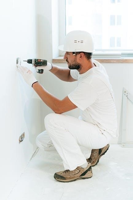
2.2 Personal Protective Equipment
Always wear appropriate personal protective equipment (PPE) during installation. This includes safety glasses, gloves, and a hard hat to prevent injury from falling objects or debris. Steel-toe boots are recommended to protect against heavy tools or equipment. Ensure all PPE meets local safety standards and is in good condition. Proper use of PPE is essential for preventing accidents and ensuring a safe working environment. Never compromise on safety by skipping essential protective gear. This equipment is vital for protecting yourself and others during the installation process.
2.3 Hazardous Materials Handling
When handling hazardous materials during TEM6 installation, always follow safety guidelines. Wear appropriate PPE and ensure materials are stored in well-ventilated areas, away from ignition sources. Dispose of waste materials like packaging and unused chemicals responsibly, adhering to local regulations. Avoid pouring chemicals down drains to prevent environmental contamination. Refer to Safety Data Sheets (SDS) for specific handling instructions. Proper storage and disposal practices are crucial for safety and environmental protection. Always comply with local hazardous material regulations.

Tools and Materials Required
Essential tools include a drill, screwdrivers, wrenches, and pliers. Materials needed are mounting hardware, electrical connectors, and sealants for a secure and efficient installation process.
3.1 Essential Tools for Installation
The essential tools required for TEM6 installation include a drill, screwdrivers, wrenches, and pliers. Additional tools like wire cutters, strippers, and a multimeter may be needed for electrical connections. Ensure all tools are in good condition to avoid installation issues. Mounting hardware and fasteners are also necessary for securing the unit. Proper tools ensure a safe and efficient installation process, adhering to manufacturer guidelines and safety standards. Always refer to the manual for specific tool recommendations tailored to your TEM6 model.
3.2 Required Materials and Components
The TEM6 installation requires specific materials and components for proper setup. These include mounting brackets, fasteners, and electrical connectors. Ensure compatibility with your TEM6 model, such as TEM6 A0B24H21S or TEM6 A0D48H41SB. Additional components like drain pans and support brackets may be necessary, as outlined in the manual. Verify all parts are included in the packaging or purchased separately. Correct materials ensure a secure and functional installation, adhering to safety and performance standards. Always refer to the manual for a detailed list of required components.
Installation Process
The installation process involves site preparation, mounting, and electrical connections. Ensure the location is suitable and follow the manual’s guidelines for a secure setup. Proceed methodically to avoid errors.
4.1 Site Preparation and Location Considerations
Ensure the installation site is clear, level, and free from obstructions. Verify that the location complies with local building codes and regulations. Check for proper drainage to prevent water accumulation. Ensure accessibility for maintenance and future servicing. Confirm the area is well-ventilated and suitable for the unit’s operation. Avoid areas prone to moisture or extreme temperatures. Follow the manufacturer’s guidelines for optimal placement and functionality. Proper site preparation ensures safe and efficient installation of the TEM6 unit.
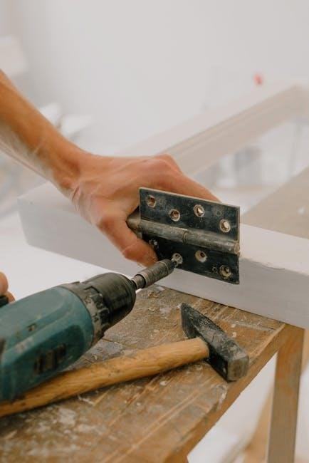
4.2 Mounting the TEM6 Unit
Ensure the TEM6 unit is securely mounted to prevent movement during operation. Position the unit in a level, stable location, such as a wall or floor, using the provided mounting brackets. Verify the unit is properly aligned and balanced to avoid vibration. Use appropriate anchors or screws to secure the unit firmly. Check for proper clearance around the unit to ensure airflow and maintenance accessibility. Follow the manufacturer’s guidelines for specific mounting requirements. Proper installation ensures safe and efficient operation of the TEM6 unit.
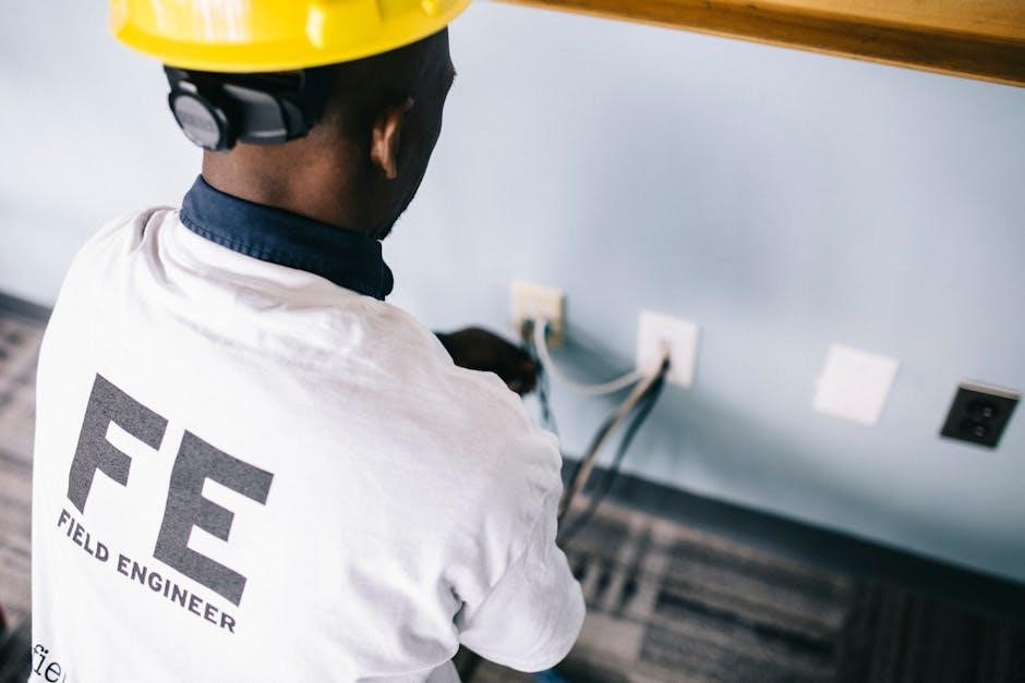
4.3 Electrical Connections and Wiring
Follow the wiring diagram and manufacturer guidelines for proper electrical connections. Ensure all power supplies and controls are connected accurately. Verify voltage compatibility and secure all wiring connections tightly. Use appropriate circuit breakers or fuses as specified. For models like TEM6 A0B24H21S, ensure the correct wiring configuration to avoid malfunctions. Double-check connections for controls and sensors. Use a licensed electrician if unsure. Proper electrical setup ensures safe and efficient operation of the TEM6 unit. Always refer to the wiring diagram for specific instructions.
4.4 Specific Model Considerations (TEM6 A0B24H21S, TEM6 A0D48H41SB)
For the TEM6 A0B24H21S, ensure proper wiring configuration to prevent malfunctions. The TEM6 A0D48H41SB requires a drain pan support bracket installed on the top, near the drain ports. Follow the specific guidelines for each model, as outlined in the manual. Proper installation ensures optimal performance and longevity. Always refer to the model-specific instructions for precise setup requirements. These considerations are critical for safe and efficient operation of the TEM6 unit. Consult the wiring diagram for detailed configurations unique to each model.
Wiring Diagram and Electrical Setup
Refer to the wiring diagram for precise connections. Ensure power supplies are correctly linked, and follow model-specific instructions for electrical configurations to guarantee safe and efficient operation.
5.1 Understanding the Wiring Diagram

The wiring diagram provides a visual representation of electrical connections for the TEM6 series. It outlines the flow of power and control signals between components. Color-coded wires and symbols ensure clarity. Always match wire colors and terminal labels to avoid errors. Consult the manual for model-specific configurations, such as TEM6 A0B24H21S or TEM6 A0D48H41SB. Verify connections before powering up to ensure safe and proper system operation. Adhere to local electrical codes and safety guidelines during installation.
5.2 Connecting Power Supplies and Controls
Before connecting power, ensure the system is disconnected. Connect the power supply to the designated terminals, following the wiring diagram. Attach control wires to their respective terminals, ensuring correct polarity and voltage. For models like TEM6 A0B24H21S and TEM6 A0D48H41SB, verify specific configuration requirements. Secure all connections firmly to prevent loose contacts. Double-check the wiring diagram for accuracy and ensure compliance with electrical standards. Power up the system only after confirming all connections are correct.
Post-Installation Checks and Testing
After installation, perform initial start-up and functionality tests. Check airflow, verify system operation, and ensure all components function as expected.
6.1 Initial Start-Up and Functionality Test
After completing the installation, turn on the power supply and ensure the system starts up smoothly. Check for unusual noises or vibrations. Test all airflow settings to confirm proper functionality. Verify that the system responds to control inputs and operates within specified parameters. Refer to the wiring diagram to ensure all connections are correct. Monitor temperature and airflow levels to confirm they meet design specifications. Document any issues and address them promptly. If problems arise, consult the troubleshooting section or contact technical support.
6.2 Airflow Testing and Adjustments
After initial start-up, perform airflow testing to ensure proper system performance. Use a manometer or airflow meter to measure airflow rates across the evaporator coil and duct system. Compare measured values with manufacturer specifications. Adjust damper positions or fan speeds as needed to achieve balanced airflow. Refer to the wiring diagram to verify control signals for airflow modulation. Test the system under all operating modes to ensure consistent performance. If airflow is uneven, inspect for obstructions or leaks in the ductwork. Retest the system after adjustments to confirm optimal functionality.

Maintenance and Service Procedures
Regular maintenance ensures optimal performance and longevity. Schedule routine inspections, clean filters, and check drainage systems. Refer to the manual for detailed service procedures and intervals.
7.1 Routine Maintenance Tasks
Perform routine inspections every 3-6 months. Clean filters monthly to ensure proper airflow. Check and clear condensate drains to prevent blockages. Inspect electrical connections for wear or damage. Lubricate motor bearings annually if required. Replace worn-out belts or pulleys promptly. Ensure the unit is free from dust and debris. Always follow manufacturer guidelines for specific maintenance tasks to maintain efficiency and prevent system failures.
7.2 Filter Cleaning and Replacement
Regularly clean or replace air filters to ensure optimal performance. Turn off power before servicing. Remove filters and wash with mild detergent if reusable. Replace disposable filters every 1-3 months. Inspect for damage or wear; replace if necessary. Reinstall securely after cleaning or replacement. Follow manufacturer’s recommendations for filter type and maintenance frequency. Proper filtration enhances airflow, efficiency, and indoor air quality, preventing system strain and potential failures.
7.3 Drainage System Maintenance
Regularly inspect and clean the drainage system to prevent blockages. Ensure drain pans and pipes are clear of debris. Check for proper water flow and verify connections are secure. If equipped, inspect condensate pumps for function. Test drain operation during maintenance visits. Address any leaks or corrosion promptly. Follow manufacturer guidelines for chemical cleaning solutions. Proper drainage prevents water damage and maintains system efficiency. Schedule annual checks to ensure optimal performance and prevent potential issues during operation.

Troubleshooting Common Issues
Identify common issues by checking error codes and system performance. Reset the unit if necessary and adjust settings as required. Consult the manual for detailed solutions.
8.1 Identifying and Diagnosing Problems
Start by reviewing error codes displayed on the control panel. Check for unusual noises, reduced airflow, or inconsistent temperature output. Inspect electrical connections and ensure proper installation. Verify that filters are clean and unblocked. If issues persist, consult the wiring diagram to trace potential faults. Pay attention to system performance during startup and operation. Document symptoms for accurate diagnosis. Refer to the troubleshooting section in the manual for specific solutions tailored to the TEM6 series.
8.2 Resetting the System
To reset the TEM6 system, first disconnect power at the circuit breaker or switch. Wait 30 seconds to ensure all components are powered down. Restore power and check the control panel for error codes. If issues persist, consult the troubleshooting guide in the manual. Resetting may resolve minor malfunctions without further intervention. Always ensure the system is cool and safe to handle before accessing internal components. Follow manufacturer guidelines to avoid damage or voiding the warranty.
8.3 Common Error Codes and Solutions
The TEM6 system displays error codes to indicate specific issues. Code E1 typically signifies a sensor malfunction, while E2 points to a communication error between components. Code E3 usually relates to drainage problems. To resolve these, check sensors for blockages, ensure proper wiring connections, and clean the drainage system. Reset the system after addressing the issue. Refer to the manual for a full list of codes and detailed solutions. Always follow manufacturer guidelines to prevent further malfunctions and maintain system efficiency.
Thank you for following the TEM6 installation manual. Proper installation and maintenance ensure optimal performance and safety. Refer to the guide for future troubleshooting and servicing needs.
9.1 Summary of Key Installation Steps
The TEM6 installation process involves site preparation, unit mounting, electrical connections, and post-installation checks. Ensure all safety measures are followed, and components are correctly connected. Verify airflow settings and test functionality before finalizing. Proper adherence to these steps ensures efficient and safe operation of the TEM6 air handler, as outlined in the manual and supported by troubleshooting guides for any issues encountered during or after installation.
9.2 Importance of Following Manufacturer Guidelines
Adhering to the manufacturer’s guidelines is crucial for ensuring the TEM6 air handler operates safely and efficiently. Proper installation and maintenance procedures, as outlined in the manual, help prevent system malfunctions and extend equipment lifespan. Failure to follow guidelines may void warranties, compromise safety, and lead to performance issues. Always refer to the official TEM6 installation manual for specific instructions tailored to your model, ensuring compliance with safety standards and optimal system functionality throughout its service life.